Multimeter – Your Onboard Electrical Tester
The multimeter function, also known as a volt-ohm-milliammeter (VOM), is a powerful tool built into the V500 Pro. It allows you to measure key electrical properties such as voltage, resistance, current, and diodes in your vehicle.


For example, if you own a 2016 Toyota Corolla and notice dim headlights, you can use the V500 Pro multimeter to measure the battery voltage. If the reading drops below 12V, it may indicate a weak battery that needs charging or replacement. With this feature, diagnosing electrical issues becomes faster, easier, and more accurate.
The bottom of the interface is the functional area, from left to right are: Voltage, Resistance, Diode, Current, Frequency and Polarity.
Kindly note: Please ensure correct wiring when making connections: connect positive to positive and negative to negative. Incorrect wiring may cause damage to the device.
How to Operate the V500 Pro Multimeter
You can press the "Left" or "Right" button to select the test mode.


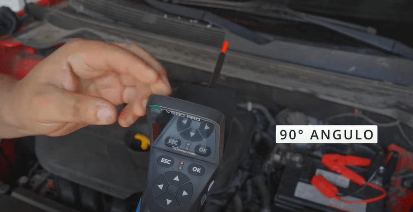
(1) Voltage (VDC): Connect the probe clip (auxiliary ground lead) to the negative pole, and connect the probe tip to the mea- sured voltage.
DC voltage: In this mode, touch the probe tip to a circuit. The LCD will display the DC voltage with 0.1V resolution.
AC voltage: In this mode, touch the probe tip to a circuit. The LCD will display the maximum voltage, minimum voltage, and frequency.


(2) Resistance (OHM): Connect the probe clip (auxiliary ground lead) to one side of the Resistance being measured, and the probe tip to the other side.
In this mode, touch the probe tip to a circuit. The LCD will show the resis- tance between the probe tip and the auxiliary ground lead.

(3) Diode (DIO): Connect the probe clip (auxiliary ground lead) to one side of the Diode being measured, and the probe tip to the other side. Meanwhile it will display the voltage and show Positive and Negative of Diode.
In this mode:
• Connect the probe tip to the positive terminal of the diode.
• Connect the auxiliary ground lead to the negative terminal.
• The screen will display the forward voltage drop, indicating correct forward bias.
•If you reverse the connections (tip to negative, ground lead to positive), the screen will not display a voltage, indicating correct reverse bias.


(4) Current (AMP): The probe is connected in series in the circuit under test, it will display the current value.
(5) Frequency (HZ): Display the frequency of the measured signal and duty cycle value.
(6) Polarity: Display whether the current measured line is positive or negative.
For more:
NOTE:
When testing the current, make sure the wires are in series connection, not in parallel connection. If they are in parallel connection, it will cause the device to trigger the overload protection and then restart. If you have any questions while using the V500 Pro, feel free to contact us at service@vdiagtool.com


